How to Set Up Periodic Boundary Condition in ANSYS FLUENT
- Dec 2, 2024
- 3 min read
Updated: Jan 25
Periodic boundary condition (periodic BC) is very useful and time saving feature when you working with repeating geometries. With Periodic BC, you will have less number of mesh elements, so faster simulation to get results.
In this example, we have 25mm diameter, 50mm long smooth pipe and we will see how to avoid errors while setting up periodic boundary conditions.
Let's start with Fluent Meshing, then I will show how to match periodic faces in classical meshing window.
After completing "Generate Surface Mesh".
Right Click to "Generate Surface Mesh", and select "Set Up Periodic Boundaries"

And "Set Up Periodic Boundaries" will shown in workflow.

Select it, and now set up based on your model. Since for this simulation, we have smooth straight pipe, so we will select type as “Translation”.

Leave remaining selections as it is and select periodic faces, here we will select “inlet” and “outlet” and click “Set Up Periodic Boundaries”.
In the context of this smooth pipe example, remaining parts are arranged as below. You may need to change based on your simulation requirements.


When meshing is done, click “Switch to Solution” and “Setup” interface will open.
In “Setup” section, we will define periodic condition using fluent console.
Write below command to console and press “Enter”
define/boundary-conditions/modify-zones/make-periodic
In fluent you can use below shortcuts, as well.
define/bc/mz/mp

Now we will define “Periodic zone” by writing ID of related face.
Select “Boundary Conditions”, and select “inlet”. We will write ID “12” for inlet and “30” for outlet for this simulation.

In console window, write “12”, and press Enter.

Write “30”, again Enter.

As I previously stated, this specific problem is translational, so we will write “no”, or just “n” and press Enter. Other two questions will be “Yes” or just “y”. Now we are all set for periodic boundary condition.

At this stage you may get below error and here how you can solve it.
Warning: Number of elements does not match between zone 12 and 13.
Error: Failed to make zones periodic.
Error Object: #f
Here I repeated fluent meshing without defining “Set Up Periodic Boundaries”, so ID numbers are different.

To solve that, we need to identify FLUENT that “inlet” and “outlet” faces are periodic.
Define “inlet” and “outlet” as “interface” by following steps shown in below picture. Start with right click.

Double Click Mesh Interfaces>>Manual Create

Write “Mesh Interface” name, select “inlet”, and “outlet”, or names that you defined as starting and ending faces.
Select “Periodic Boundary Condition”
Deselect “Auto Compute Offset” and set your “Offset” value, for this pipe example, pipe length is 0.05m. My main coordinate started at (0,0,0), ends at (0.05, 0, 0 ). Click "Create/Edit..."

Now we made mesh interface.

And we can see that periodic condition is defined.
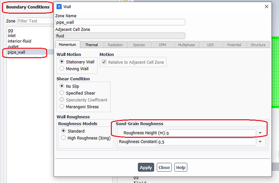
Now you can continue to define boundary conditions by clicking “Periodic Conditions…”

Now, let's see how to define in classical Meshing interface.


We have higher coordinate system, and need lower one.

And final step is match all yellow writings with related face and coordinate systems.
Higher Geometry Selection: Inlet face, or what ever you named your face (or edge if you have 2D case) that flow starts.
Lower Geometry Selection: outflow face.
Transformation: here our example is not a circular, so we choose "Arbitrary"
Higher Coordinate System: Global Coordinate System
Lower Coordinate System: New Coordinate System thtat we created.
Now we are all done to make inlet and outlet mesh to be matched. Remaining mesh operations (like inflation, body sizing etc.) depends on your case.
When you completed meshing, you can continue to Setup part with defining periodic condition using same command and all steps are same.
define/boundary-conditions/modify-zones/make-periodic
or
define/bc/mz/mp
For more solutions, you can make comments below.


Comments