Smooth pipe, turbulent flow, constant heat flux
- Dec 5, 2024
- 3 min read
Updated: Jan 25
In this article, I will share basic smooth pipe simulation using ANSYS FLUENT. Below, you will learn:
How to simplify geomety, and why it is important?
How to understand you have enough/right mesh for your simulation?
How to setup periodic boundary condition?
How to get Nusselt Number?
At the end, we will compare hand calculation and numerical result which is called verification, to see how simulation differs from formulation.
We have basic smooth pipe with below fluid properties which has 1.1m lenght and I will focus on fully developed region. Here is the first property, I don't need to simulate full length (which approximately 1m for fully developed region) because I have repeating, continues geometry, so I can only simulate small portion of it to get Nusselt number or pressure loss. To define it to ANSYS, I will use Periodic Boundary which is simply defining FLUENT that inlet and outlet of the geometry is periodic/repeating.


In any simulation, simplification is crucial that saves time, so does computation power. For instance, in this problem, I am dealing with fully developed region and want to get Nusselt number. Here I can simplify this problem to simple 2D case, and again, with this approach I will get my results faster. Here I will go with number 3.

In meshing part, I will give names to edges, so Setup part will recognise it and I will be able to define boundary conditions.
One important trick is Match Control. Even if mesh looks symmetrical, in some cases it is better to use Match Control to make inlet and outlet faces/edges to same(matching) mesh(node). This generally needs to be done while working with 3D geometries. If you get and error when defining periodic bc at Setup step, Match Control may solve this.

Then how to understand number of mesh is enough? Well, in simulation, most common words are "it depends", because it is.
General approach:
Start with coarse mesh
Get result (for this example, Nusselt number).
Increase number of mesh.
Get result.
Make a graph with these results.
Keep increase your number of mesh.
And add it your result to your graph.
And see at which number of mesh does not make significant change on your result.
But, keep in mind below things:
You don't have to increase number of mesh for your all domains, which will increase computation time. If possible, separate your complex geometry from rest of your domain, so you will only need to increase number of mesh around related body/wall.
General approach in growth rate is 1.5 in increasing number of mesh element. If your first simulation have 100k mesh, next one will be 150k, and so on.
For this problem I want to see Nusselt number. This is a heat transfer problem, and flow is turbulent, then I need finer mesh close to the pipe_wall. What is the level of dense, what will be the first layer height needs to be calculated using y-plus calculator.(You can use online y-plus calculators)
Mesh quality is really important and needs to be in a certain range, because analysis results are highly depend on mesh quality. General approach, make orthogonal quality > 0.1, skewness < 0.9.

When geometry become compicated, it will become hard to get high quality mesh. One way to make your mesh easy to control and to get reasonable quality, using slice on your geometry. You can split your face or slice your 3D geometry to get control on your focus area/region/zone.


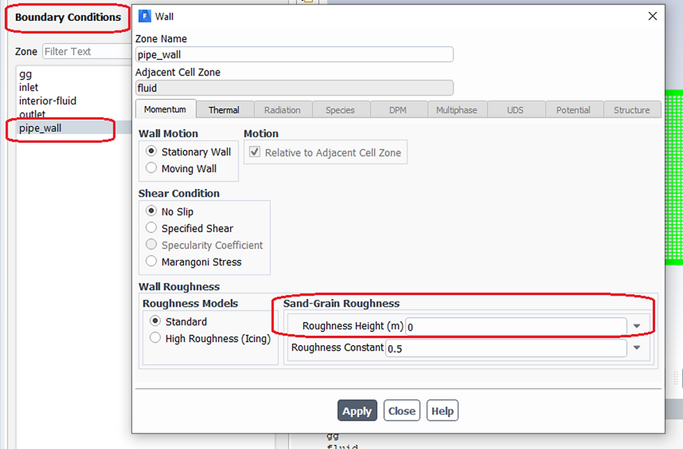
Let's go back to our main case, and see how to define periodic boundary in FLUENT Setup. In this article I have explained how to set up.
How we get Nusselt Number?
In theory, turbulent flow in a smooth pipe will be got by using below formula:

n=0.4, for heating
You may find calculation details in shared PDF. Here I will show little but important details to get correct Nusselt number.
In FLUENT interface, we use Reference Values to calculated desired results. Below I marked what we need to get Nusselt number.

Next, we will compare the results and verify.


Comments