Pipe Pressure Loss with Different Pipe Materials
- Dec 8, 2024
- 2 min read
Updated: Jan 25
This is the first article in this website!! I shared hand calculations and below, I will share some key steps in ANSYS Fluent.
Let's say we have 3 different pipe/tube materials and want to compare pressure loss. Later we will compare with hand calculation vs. Fluent result.

I will not go deep into all analysis steps but I will share some points.
As usual, we start desinging with a selected plane. Since here I designed 50mm pipe piece as this simulation is periodic BC, you can do what ever you want, but advantage of periodic BC is to reduce mesh, so does reducing computation time. Keep in mind that while defining your geometry length.
Meshing stage is another important step, since your result is highly depend on your mesh quality. Make sure you check your related mesh quality, generally common checks are Orthogonal Quality, Skewness and Aspect Ratio. Also make sure that your inflation layer is enough to solve boundary layer. For this type of problem, you can use online y+ calculators as first layer height.
Another step is mesh independence, since we have small geometry for this problem, checking results with increasing mesh element number is general approach in simulation.
You can find some details in PDF, but here I want to show how you can define pipe roughness in Fluent Setup.
You just need to edit related boundary condition and change Roughness Height.
Default value is 0 (which can be considered as Case 1, Glass, for this example).
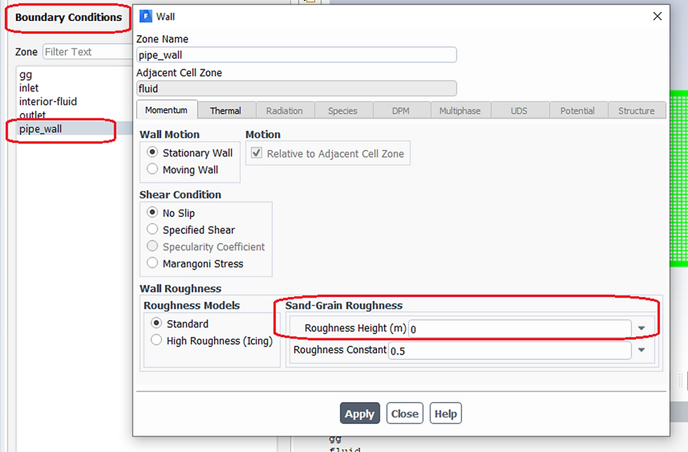
Figure 1
After running simulations with different roughness height, it is time to compare results and talk about it.

Before evaluating these results, I need to remind you that there are limited numerical cases that you get %100 match with theory, and even your results in this example can slightly differ from my results. All these difference may come from mesh quality, number of mesh, number of nodes etc. so there are always some level of accaptance in CFD simulations and this is highly dependent on experimental results which arises another question, is this experiment well established?
With Table 2, we can say that theoretical and numerical results are close and can be accepted as verified for Glass, and Steel (Commercial, new). Rusted steel error looks higher than others and with this kind of simulations we can play with mesh, number of inflation layer and first layer thikness since that material has 2mm roughness height and inflation may need to be considered.
Feel free to make some comments and share your questions and ideas about this example.
Reference
[1] Frank M. White, Fluid Mechanics, 4th Edition, Table 6.1


Comments